System Hazard Analysis (SHA) is a comprehensive safety assessment method used to identify and evaluate hazards at the system level. Unlike component-level or preliminary analyses, an SHA focuses specifically on how integrated systems behave under both normal and abnormal conditions, examining how complex subsystem interactions, functional failures, or environmental interfaces lead to unsafe outcomes.
This analysis is essential in safety-critical domains where complex systems operate in highly dynamic environments, including aerospace, rail, automotive, energy, defense, and healthcare. By executing a structured SHA, organizations can understand systemic risks, prioritize design mitigations, and ensure strict compliance with international safety standards.
Why the SHA Matters in the Engineering Lifecycle
Engineering teams frequently treat the SHA as a static compliance document required solely to satisfy the expectations of industry assessors. However, completing an SHA early during active development provides immense engineering value. It drives primary architecture decisions, helping teams anticipate failures before they are locked into physical hardware. This proactive analysis prevents late-stage safety findings, which dramatically shortens overall design timelines and reduces development costs.
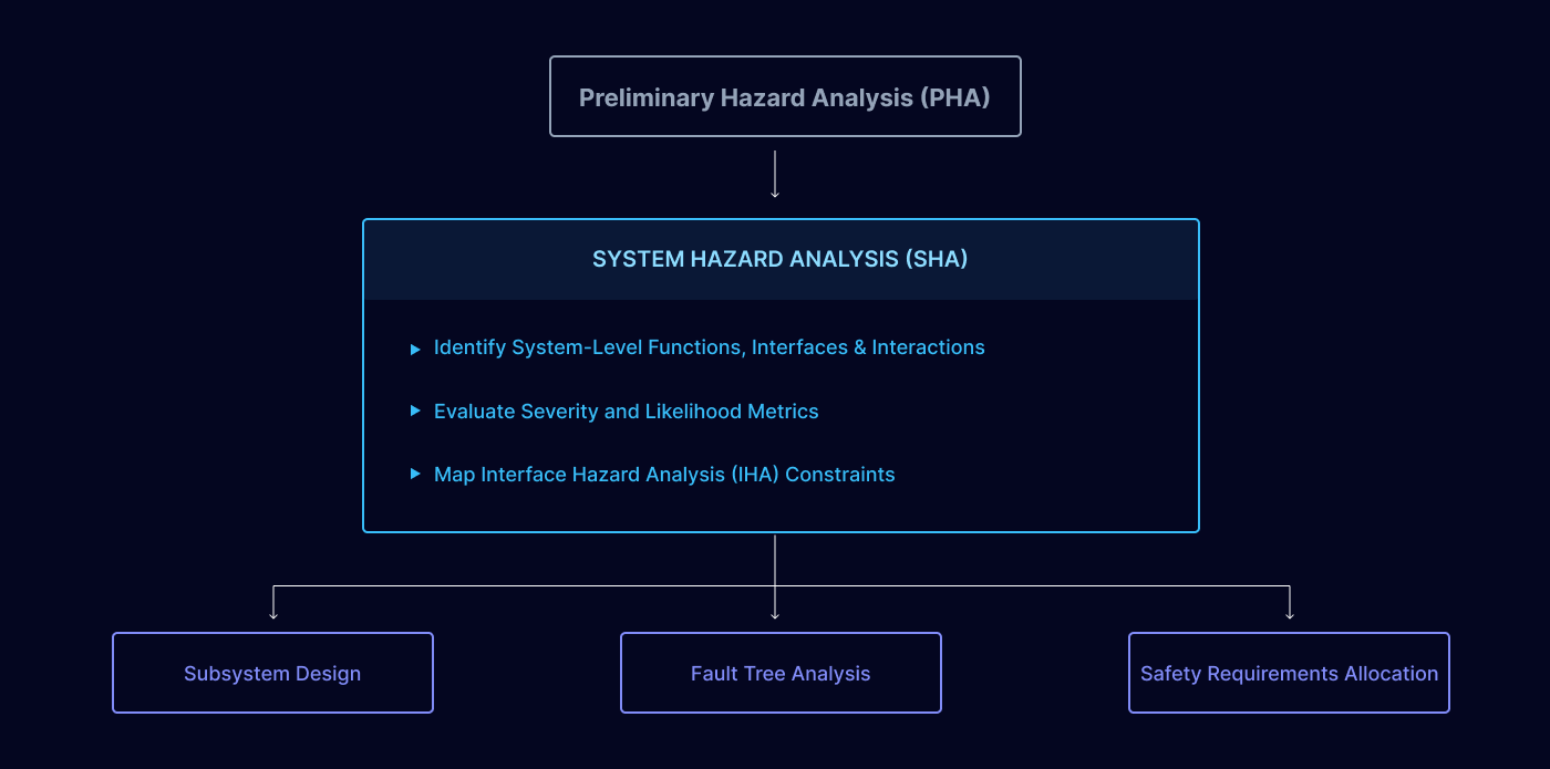
The SHA is performed immediately following the Preliminary Hazard Analysis (PHA). The outputs of the SHA feed directly into lower-level subsystem design decisions, top-down Fault Tree Analysis (FTA), and Safety Requirements Allocation. It must be completed during the early stages of system requirement definition and architecture refinement. At this lifecycle stage, the SHA operates at a comparable architectural level to an Interface Hazard Analysis (IHA), making it standard engineering practice to combine the IHA directly into the SHA repository.
Cross-Industry Functional Safety Standards
The core intent of a system-level risk assessment remains identical across all safety-critical domains, though the specific nomenclature and compliance frameworks vary by industry. The SHA acts as the primary mechanism to demonstrate fulfillment of these standard requirements:
Rail Transit Systems:
Governed by EN 50126, EN 50716, and IEC 62278.
Aerospace Engineering:
Managed via ARP4761, DO-178C, and MIL-STD-882 compliance pathways.
Automotive Systems:
Directed by ISO 26262 and SAE J3061 cybersecurity/safety frameworks.
Energy & Power Infrastructure:
Regulated under industrial automation master standards including IEC 61508, NERC CIP, and ISO 31000.
Healthcare & Medical Devices:
Anchored to ISO 14971 risk management and IEC 62304 lifecycle software requirements.
Defense Platforms:
Controlled by MIL-STD-882E systemic safety practices and NATO AOP-15 guidelines.
Key Steps in Conducting a System Hazard Analysis
1. Define System Boundaries (Clause-Specific Context)
The analysis requires mapping out all system functions, physical and logical interfaces, and the complete operational context. The SHA author holds direct responsibility for ensuring that each boundary is explicitly defined and formally agreed upon by all interfacing parties to eliminate analytical gaps. If the end user or integrator is not yet defined or known, specific operational constraints related to the final product integration must be documented and shared via requirements management tools or comprehensive user manuals.
2. Collect Inputs
A complete, systematic SHA cannot be performed in an engineering vacuum. The analysis requires three primary technical baselines: documented system requirements, a verified system architecture description, and historical data or past experiences compiled from similar system developments. These inputs are critical to eliminate structural gaps when defining safety requirements early in the design cycle.
3. Identify Systematic Hazards
Engineers utilize brainstorming, historical field data, and structured analysis techniques to define hazards across the entire product lifecycle, explicitly evaluating manufacturing, active use, repair, and end-of-life decommissioning phases. Hazards must be defined at a high system level relative to the established boundaries.
System-Level Principle: If you are developing a train control subsystem, an intermediate failure like an "overspeed condition" is an operational state, not the final hazard; the final hazard must be clearly stated as a "collision" or "derailment" so that total system risk can be assessed accurately.
Every system function and its associated requirement must be systematically evaluated. All potential failure modes for each function must be documented to demonstrate which functions are safety-critical and which require external safety functions to provide adequate protection. No system function can be omitted from documentation until the SHA systematically determines that further analysis is unnecessary.
4. Analyze Hazard Causes and Effects
This step tracks failure modes, environmental conditions, and human interactions. The effect of a failure must be documented at the local boundary level as well as one level above the immediate area of responsibility. For example, if a subsystem failure results in a train operating at overspeed, the cascading effect of that overspeed state must be evaluated and documented at the total system level.
5. Assess Risk Profiles
Severity and likelihood are evaluated by applying the specific risk matrices defined within the project's Safety Plan, which are typically derived from the applicable industry standard. Because system-level risk assessments can be subjective due to limited empirical data early in the design phase, engineers must thoroughly document all underlying assumptions for each failure mode. This risk assessment serves as the direct input for planning mitigation strategies.
6. Recommend Technical Mitigations
Propose design changes, active safety features, or administrative operational controls derived from the target Safety Integrity Level (SIL) or equivalent metric. Mitigations are formulated as safety requirements injected directly into the system design, lower-level subsystems, hardware components, or software code. The best-engineered safety requirements must contain three structured parts:
The actual technical requirement containing a single, standalone "shall" statement.
A clearly defined hazard description that the requirement intends to mitigate.
Explicit engineering guidance on implementing the mitigation method based on existing system knowledge.
7. Document and Review Loop
Maintain strict requirement traceability as the architecture evolves, tracking and auditing safety requirements to verify proper implementation, verification, and validation. Reviewing each safety requirement directly with the design engineers is critical to guarantee alignment on design intent and mitigation behavior, as an incorrectly implemented safety requirement is functionally useless.
Final Blueprint Considerations
System Hazard Analysis acts as the primary bridge between early hazard identification and detailed failure analysis, ensuring that functional safety is built into the system architecture from the ground up. Whether you are designing a high-speed train control network, a surgical robotic arm, or an aerospace flight control system, executing a thorough SHA allows your organization to anticipate systemic risks, protect human lives, and successfully navigate regulatory audits.
Functional Safety: Managing Risk in Complex Systems
Functional safety relates to the architectural ability of vehicles and industrial machines to operate correctly and dynamically prevent accidents. Rather than relying on static structural protections, these active systems are designed to detect faults and respond in a predictable manner, minimizing hazards to human personnel and the surrounding environment. To implement functional safety, engineering teams embed active safety mechanisms designed to detect, isolate, and manage system failures before they escalate into dangerous conditions. This discipline demands an engineering lifecycle focused on systematic risk assessment, strict system design principles, robust component selection, rigorous testing, and continuous operational monitoring.
Cross-Industry Application Profiles
Active safety control plays an indispensable role in reducing the probability of system failures across multiple safety-critical industries:
Automotive Systems:
Inside passenger vehicles, control systems like airbags, Anti-lock Braking Systems (ABS), and Electronic Stability Control (ESC) must perform reliably under all defined operational profiles. Because the structural failure of these active electronics can cause catastrophic consequences, including severe injury or loss of life, functional safety frameworks guarantee that hardware-redundant paths or fallback corrective actions activate instantly if a fault manifests.
Aerospace Platforms:
Commercial and military aircraft rely heavily on tightly integrated electrical and electronic avionics loops to handle critical flight phases, navigation, and cockpit communications. A functional failure within these flight control computers can precipitate immediate, catastrophic accidents, making functional safety compliance an absolute prerequisite for flight certification.
Industrial Automation:
Modern manufacturing plants and chemical processing facilities utilize autonomous machinery interfaced directly with programmable control systems. An unmitigated control malfunction can cause immediate worker injuries, localized equipment destruction, and highly expensive operational stoppages. Embedding active functional safety measures isolates dangerous actions to prevent these factory floor incidents.
Core Pillars of Functional Safety Architecture
Safety Integrity Level (SIL):
Regulated primarily under the master standard IEC 61508, a Safety Integrity Level serves as a quantitative measure of a safety function's target reliability in preventing dangerous failures. These designations range from SIL 1, representing the lowest safety integrity tier, up to SIL 4, which dictates the highest safety integrity level and mandates the most stringent testing metrics, diagnostic verification, and hardware redundancy.
Risk Assessment Frameworks:
Identifying potential systemic hazards, analyzing underlying risk parameters, and evaluating the cascading consequences of control loop failures form the baseline of any functional safety program. These early lifecycle risk assessments determine which specific safety functions are necessary and calculate the exact levels of hardware redundancy or fault tolerance required for individual components.
Redundancy and Fault Tolerance Strategy:
Redundancy involves duplicating critical components (such as installing parallel sensors or backup power modules) so that an alternative path instantly assumes control if the primary element suffers a random failure. Fault tolerance defines the system's structural capability to maintain secure, continuous operation despite the active presence of specific internal faults. These mitigation strategies are executed via physical hardware solutions or software algorithms like real-time error detection logic. However, standard hardware redundancy typically does not protect against Common Cause Failures (CCF) where a single trigger destroys identical channels; neutralizing CCF risks requires the deliberate implementation of design diversity.
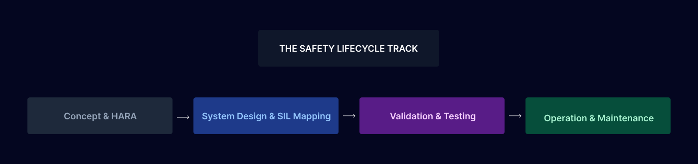
The Safety Lifecycle: Achieving systematic safety requires following a safety lifecycle, which acts as a structured, version-controlled blueprint tracking a system from initial concept development through to decommissioning. The lifecycle segments the engineering pipeline into distinct phases. Incorporating hazard analysis, technical system design, verification validation testing, active operation, and long-term maintenance to ensure safety considerations are integrated into daily engineering decisions.
The International Regulatory Landscape
Different sectors rely on specialized international safety standards to provide technical guidelines for engineering high-integrity electronic control loops:
IEC 61508 (Industrial Master Standard):
The foundational, globally recognized standard for electrical, electronic, and programmable electronic safety-related systems. It covers the entire lifecycle from initial design to final decommissioning, dictating explicit requirements for risk management, hardware redundancy calculations, and verification steps.
ISO 26262 (Automotive):
A specialized standard focused on the functional safety of electrical and electronic subsystems embedded inside passenger road vehicles. It defines strict process requirements covering automotive hazard analyses, risk assessments, and targeted functional safety validation tracks.
DO-178C and DO-254 (Avionics):
The primary compliance benchmarks for aviation electronics. DO-178C mandates strict safety guidelines for avionics software development, while DO-254 governs high-integrity hardware architectures.
ISO 13849 (Machinery Automation):
Applicable to the control networks of industrial machines and automated factory subsystems. It provides precise guidelines to design, implement, and validate safety-related parts of control systems.
Engineering Implementation Milestones
Sustaining high functional safety demands a unified approach integrated across every distinct sub-phase of product development:
System Design Integration:
Safety functions must be architected early in the system layout phase. This involves selecting components that meet documented reliability targets, building hardware redundancy into high-risk critical paths, and proving that the safety systems can successfully detect and respond to random internal failures.
Fail-Safe Designs:
Systems should be engineered to fail only in a controlled, non-hazardous manner when a fault occurs. In automotive engineering, a fail-safe strategy might trigger controlled airbag deployment or apply secondary braking paths during an electronic component failure.
Validation and Testing Tracks:
Before a system can be certified as safe, it must undergo rigorous verification testing to confirm safety mechanisms activate according to specifications. This requires functional testing to verify normal operational limits and physical fault-injection testing to prove the system transitions to a safe state during active failure conditions.
Monitoring and Field Maintenance:
Once equipment enters active service, continuous monitoring protocols are required to track system telemetry and isolate emerging anomalies. Adhering to preventive maintenance schedules, executing secure software safety updates, and conducting routine performance audits are mandatory to sustain safety across the entire product lifecycle.
Primary Challenges in Modern Functional Safety
Escalating System Complexity:
As modern systems become highly interconnected and dependent on advanced electronics, distributed software code, and dense sensor networks, verifying every internal component becomes exponentially difficult. An isolated component failure can trigger cascading effects across a network, demanding intricate architectural design and exhaustive testing matrices to guarantee overall system integrity.
Evolving Technological Threats:
The emergence of connected Internet of Things (IoT) ecosystems introduces complex cybersecurity risks, while the introduction of autonomous systems presents novel challenges to traditional functional safety paradigms. Connected control networks face a higher probability of malicious cyberattacks or external interference, forcing engineers to implement overlapping security and safety protocols.
Complex Regulatory Compliance Navigation:
Managing compliance across a diverse landscape of evolving international standards can become highly complex, particularly for manufacturers deploying systems across multiple geographical markets or cross-industry sectors. Continuous adherence to applicable safety standards is vital not only to protect human life, but to satisfy strict legal requirements and clear international commercial barriers